
Also available in presentation mode…
General description
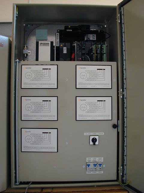
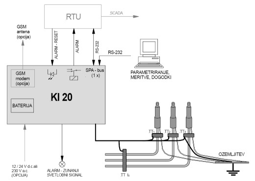
The KI 20 fault current indicator is designed to locate earth-faults (phase to earth) or short-circuit (phase to phase) in cable medium-voltage networks. With the fault indicator KI 20 it is also possible to read the measured values of line-currents and residual current via the serial port. The device is used for mounting indoors, for example in the substations or in the rooms in which the medium-voltage cables are accessible. It can be used in networks with isolated or impedance earthed neutral as well as compensated networks. Fault-current detection is based on the measurement of the lines' phase-currents and residual current. Currents are measured by split-core current transformers, mounted on an insulated section of the cable.
Technical data
- Earth-faults (I0>) and short-circuits (I>) detection (temporary and permanent faults);
- Phase currents (L1, L2 and L3) and residual current (I0) value reading;
- Current transformers: 3 x 600A/1A*, 1 x current summation transformer 250A/1A*; cable length: 4 m*; split-core type for mounting on an insulated medium-voltage cable;
- RS-232 interface for setting the parameters and for communication with the RTU;
- Fault-signalling:
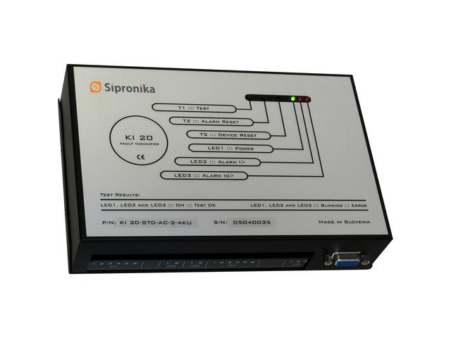
- two LED's on the casing indicating the fault type: earth-fault and/or short-circuit;
- one no-voltage output relay or optional two output relays for indication of earth-fault and short-circuit separately;
- external-LED output, 3.6 V / 20 mA;
- RS-232 serial interface (SPA bus); events with time tags.
- Resetting possibilities:
- by timer: 0.5 .. 4 hours;
- return of the normal load-current;
- return of the normal operating-voltage (only version with the additional auxiliary a.c. power supply);
- Autotest / Reset key;
- external signal (8...30 V / 0.5...5 s);
- RS-232 serial interface.
- Setting of numerous operating parameters via switch group or RS-232 interface: detection sensitivity for I> and I0>; time delay of fault-indication, separately for I> and I0>; duration of indication; fault type indication (temporary or permanent faults, detection of autoreclosing cycles), etc;
- Multiple power-supply options: 10 - 30 V d.c., 230 V a.c., lithium battery - life expectancy 7 to 9 years. The supply option has to be defined by the customer at the ordering.
- Built-in GSM modem (as an option) for transmission of alarms and measured analog values;
- Casing for mounting on a DIN strip or onto a wall; dimensions: 90 x 160 x 72 (H x W x D);
- Electrical disturbance immunity in accordance with the IEC 61000 standards;
- Operating temperature range: –25 ... +60 °C.
* On request, other values are possible as well.
The KI 20 indicator is a microprocessor-based measurement device with numerous possibilities of adjustment to the operating parameters of the network. The device can also be programmed in different ways for its' optimal integration in the distribution automation system. The programming of operating parameters is performed by means of the switch groups or by means of a personal computer via the RS-232 serial interface (SPA-bus protocol). In addition, the serial interface allows reading of all measured values, time-tagged events and some other data of the device. The KI 20 can be easily connected to a Remote Terminal Unit (RTU) using digital signals and/or serial interface.
A GSM modem is (as an option) integrated inside the indicators' casing for signalling the faults to the distribution control centre or local staff (data transmission or SMS).
